|
| Three Methods of Generating Digital Models for a Virtual Reality Model of the Nose |
|
Andrea Stevenson Won, M.S. The complex structures of the human nose have been illustrated through both two and three dimensional models. In order to utilize VR technology, which supports stereovision, viewer-centered perspective, large angles of view, and interactivity, a series of interlocking digital models of the structures of the nose was created. These structures were the nasal cartilages, the skull and nasal bones, periosteum and mucoperichondrium. Because of the varying size, complexity, and delicacy of these structures, three different methods of creating the models were used - traditional sculpting techniques, segmented CT data, and computer modeling.
|
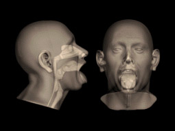
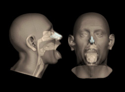
The Virtual Reality in Medicine Lab (VRMedLab) at the University of Illinois at Chicago (UIC) houses several teaching models dealing with medical subject matter. These models supplement actual operative experience on anatomical structures that are difficult to visualize, whether through their inaccessibility, delicacy, or rarity. Since nasal anatomy is delicate, complex, and difficult to visualize, with even tiny adjustments to the underlying structures resulting in radical changes to a person’s appearance, it is an ideal subject for a three-dimensional teaching model. Although there are excellent two-dimensional illustrations available, the complicated spatial relationships of the nasal structures can be difficult to grasp with only these references, and the opportunity to manipulate the structures and observe the changes that ensue is, for obvious reasons, not available. Driven by the requirements of surgeries that require the visualization of complex anatomy, researchers in other areas of anatomy and surgery have begun utilizing virtual reality technology. Virtual reality models provide a number of advantages, including stereovision, viewer-centered perspective, large angles of view, and interactivity. Models can be created that represent the outcomes of different surgical approaches, both successful and unsuccessful. Residents can rotate, and make transparent, different aspects of the anatomy in order to fully comprehend and appreciate the shapes and relationships of the various structures. In addition, distance learning is possible with virtual reality simulators, allowing residents to confer with surgeons located anywhere in today’s networked world. Our model, consisting of virtual bone, cartilage, and tissue, was placed in a pre-existing VR model of the external structures of a standard Caucasian male head and neck. It will serve as the first prototype in a larger library of detailed models of normal and abnormal nasal anatomy that will be available as a study tool for surgical residents. Creating the Models We used a previously existing virtual reality model of a male head as the basis for the creation of the new model of nasal structures. This digital model (Figure 1) was based on a physical model of the right half of a normal male Caucasian head. It was created by Ray Evenhouse, a Clinical Assistant Professor at UIC.
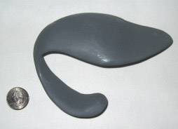
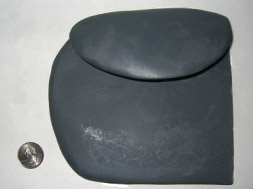
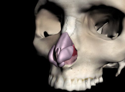
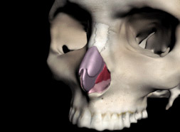
The structures we elected to create were those that were commonly encountered in surgery, and that were directly related to shaping the external form of the nose. In order to produce these structures, three different methods were used- traditional sculpture, pre-existing CT data, and the creation of models with 3D modeling programs such as 3d Studio Max™. Cartilages To create the cartilages, we used traditional sculpting techniques to create oversized physical models that were imported into the computer by computed tomography (CT) scanning. In order to adequately capture the subtleties of the shapes of the nasal cartilages, they were sculpted at 10X life size. We created only the right half of each structure so that the models would be symmetrical. Rough shapes of the left lower lateral nasal cartilage (LLNC), the left upper lateral nasal cartilage (ULNC), and the ventral portion of the quadrangular cartilage were carved out of foam and cardboard, working under the supervision of Dr. J. Regan Thomas, Francis L. Lederer Professor and Head, Otolaryngology, University of Illinois Medical Center (UICMC). The left ULNC and quadrangular cartilage were then attached. We checked these shapes for accuracy by positioning them next to the oversized nose. They were then refined until they were smooth and even. The caudal portion of the quadrangular cartilage was left unfinished in order to make it easier to fit to the bony portions of the septum, (Figures 2 and 3).
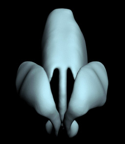
These sculptures were then CT scanned at the Radiology Department of University of Illinois at Chicago Medical Center. The data was saved as DICOM (Digital Imaging and Communications in Medicine) format data, and then brought into the program Mimics™ (version 8.1, Materialise, Inc.) to be rendered out as digital models. The surface of the models was rough, due to the varying densities of the materials in the sculptures. We cleaned and smoothed the models in Geomagic Studio™ (Version 7.0, Raindrop Geomagic, Inc.). Once the models were smoothed, we saved them as .stl (Stereolithography format) files and imported them into 3ds Max™ (Version 5.0, Autodesk, Inc). We cloned the LLNC to produce a second, identical digital model, which we then mirrored so that all of its X coordinates were inverted. The model, which consisted of the two ULNCs connected to the quadrangular cartilage, was more difficult to construct because of the transition between the left and right sides of this cartilage complex. We repeated the process of cloning and mirroring to produce two halves of a perfectly symmetrical model. These two halves were then connected, and we exported this model as a .stl file and smoothed the seams in Geomagic Studio™ (Figure 4).
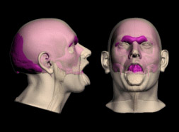
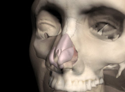
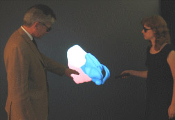
Once the models of the left and right lateral nasal cartilages and the combined upper lateral nasal cartilages and quadrangular cartilage were finished, they were placed, using the program 3ds Max™, inside a copy of the head model. We made the head model translucent so that the position of the cartilages in relationship to the surface of the nose could be seen (Figure 5). Their position was adjusted until it was determined to be accurate by Dr. Thomas.
Skull To produce the skull, we started with pre-existing data. Using the United States National Library of Medicine’s Visible Human Project® dataset, we created a template of a male skull. Unfortunately, it was not a very good match to the existing head model, (Figure 6), and required considerable manipulation.
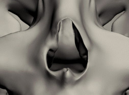
The first step in retrofitting the skull to the head was done by moving vertices on the skull model in large groups so the resulting skull fit roughly into the shape of the head. Standard tables for average tissue depths were used to produce a plausible result; however, this gross manipulation produced a skull with a rippled and tugged surface, which then had to be exported from 3ds Max™ and imported into Geomagic Studio™ for cleaning and smoothing. The skull model was moved back and forth between Geomagic Studio™ and 3ds Max™ until it fit accurately within the model of the head. Most of the effort went into getting a good result for the bone around the nasal area. The Visible Human Project® data collection methods were limited in their ability to capture small and fragile structures. This meant that the modeling of the bones of the inside of the nasal cavity was extremely defective. These bones were also very asymmetrical, common in human nasal cavities, but unsuitable for the purpose of fitting into the existing head model, which was created with idealized, symmetrical conchae. In order to properly place this anatomy, we decided to remove the left half of the skull and use the anatomical information that would thus be made available. This would also result in a symmetrical skull to match the mostly symmetrical head model. To fit in the pre-existing head model, the maxilloturbinals had to match the overlying nasal conchae and other internal nasal structures. We accomplished this by returning to the CT scan of the original head model that was the basis of the VR model. These CT slices were imported into Mimics™ and a function called “erode” was used which deleted the edges of selected areas of the nasal cavity by 3 mm. When these selected areas were rendered out as a 3-dimensional (3D) model, the new model would then fit precisely within the existing model. The space between the previously existing model and the newly created “maxilloturbinals” would approximately represent the tissue thickness in that area. We aligned the new model of the maxilloturbinals with the interior of the nose and connected the seams in Geomagic Studio™. The result was a good general model of the inside of the nose that did not include the openings of the sinuses (Figure 7).
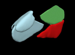
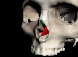
Additional Structures The other structures could be most easily created from scratch in a 3D modeling program. We created the perpendicular plate and the vomer by making simple box shapes in 3ds Max™ and moving the vertices to create approximate outlines of the two bones. For this model, the bones needed to intersect tightly with one another, and also provide a groove for the cartilaginous portion of the septum to fit into. In addition we needed to fit the perpendicular plate precisely to the rest of the ethmoid bone, and the vomer to the bony palate. To do this, we cloned these models, and the clones were then used with the Power Boolean (nPower Software) application in 3ds Max™ (Version 6.0 Autodesk, Inc.) to subtract overlapping parts of the model so that they fit tightly together (Figure 8).
We also created the periosteum and mucoperichondrium entirely from computer data. These thin layers of membrane cling tightly to the surface of the bone and cartilage, and are continuous over those surfaces. We created the periosteum on the inside of the nasal cavity by exporting all of the surfaces over which the periosteum would wrap as one object. Overlapping sections were then removed in Geomagic Studio™, and the surfaces were connected to create one continuous single surface. This was then turned into an object using the “thicken” modifier at a level of 3 mm, which created a new surface that extruded 3 mm from the original surface (Figure 9).
This fit well into the nasal cavity, with a few discrepancies that had been introduced during the process of connecting the varying surfaces. These were repaired by moving vertices in 3ds Max™. The perichondrium for the cartilages (Figure 10) was created on the original models using the “thicken” modifier in Geomagic Studio™.
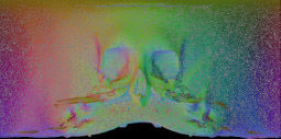
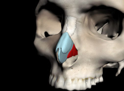
Texture Mapping In order to distinguish the different elements of the model, we chose different colors for each element. The cartilages were given the traditional light blue color, the periosteum and perichondrium were colored a glossy pink, and the vomer and perpendicular plate of ethmoid were colored red and green. All of these colors were assigned in 3ds Max™ and adjusted in virtual reality. We used a different method to create the texture map of the skull in order to provide information about the sutures and the teeth of the model. First, the skull was unwrapped in 3ds Max™ using the free Texporter plug-in developed by Cuneyt Ozdas (Figure 11).
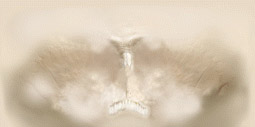
We then photographed several dry skulls and placed the photographs over this image. This composite was then painted in Photoshop™ (Version 7.0Adobe) to produce a lighter map that would look more like a living skull (Figure 12). Important landmarks like the sutures between the nasal bones were emphasized.
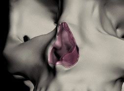
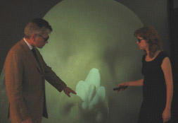
Creating the Virtual Reality Interface The virtual reality platform we created consisted of a series of steps which virtually dissected the nose. The initial step shows all of the models. A transparent texture map on the head allows the underlying structures to be seen (Figure 13). The interface then allows the viewer to step down through successive layers of tissue (Figures 14-16) until only the bare skull, vomer and perpendicular plate remain (Figure 17).
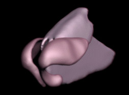
Once the model has been completely virtually “dissected” the viewer can toggle between two views. The first view (Figure 18) shows all the cartilages and the bony parts of the septum. The second view (Figure 19) shows the cartilages within the semi-opaque head. This allows the viewer to study the relationships between the cartilages and the surface contours of the face.
Conclusions It is necessary to have a wide range of techniques available in order to create an anatomical model that has so many complicated and interlocking parts. Each anatomical structure demanded a different approach depending on its size and complexity. Thus, the small, complex, and difficult-to-scan cartilages of the nose were more easily dealt with by initially sculpting them at 10X life size, which allowed their shapes to be created with great accuracy. Using CT data as the basis for the model of the skull allowed the rapid creation of a detailed and anatomically accurate model, which could then be revised digitally. The vomer, perpendicular plate of ethmoid, maxilloturbinals, periosteum and perichondrium were all structures that needed to fit closely together and to the contours of the existing head model, skull and cartilages. These were best created entirely digitally, using the main components of the model- the skull, cartilages, and head model- as guides. The use of software such as Mimics™ and Geomagic Studio™ to alter the original data was invaluable. This software allowed us to tweak the model in order to emphasize the areas of anatomical interest and of reducing the detail in areas that were not germane to the purpose of the model. This also allowed us to reduce the size of the model so that it could be manipulated within the virtual reality interface. The fact that the data came from various sources was problematic only in the instance of matching the skull from the Visible Human Project to the head model that had been previously created by Ray Evenhouse. This created some difficulties because the skull had to then be fitted to the head, instead of reconstructing a plausible face over the skull. In instances where the models to be created are not fit into a previously existing format, it would be preferable to begin with the CT data and model the rest of the structures to fit. Sculpting and digitally modeling the cartilages and additional structures to fit the skull and head were not a problem. Using combinations of traditional sculpting, information derived from segmented CT data, and digital modeling techniques, we were able to produce a useful set of digital models as seen in Table 1. These models were then refined and combined in digital modeling programs that resulted in a compatible set of digital models suitable for a virtual reality interface. These models can be viewed as a Quicktime movie on the electronic version. They can also be viewed as VRML files using the Cortona viewer, downloadable at http://www.parallelgraphics.com/products/cortona/.
Acknowledgments Ray Evenhouse, the creator of the head model on which the nose model was based, also provided advice on materials and sculpting techniques. Mary Rasmussen, the director of the VRMedLab, facilitated the development of the project. Dr. J. Regan Thomas and Dr. M. Eugene Tardy provided advice on all questions of anatomy, while Dr. Allan Ho provided insight into possible uses for the model. Finally, Bei Jin, working in the VRMedLab, developed an easy to use and intuitive interface for the model. Many thanks to them all. Andrea Stevenson Won graduated with a Master of Science in Biomedical Visualization from the University of Illinois at Chicago in December, 2005. At UIC, she focused on the three-dimensional representation of craniofacial anatomy. She interned at the Duke University Anaplastology Clinic and the Maxillofacial Prosthetics Clinic at the University of Illinois at Chicago Craniofacial Center. She was also the teaching assistant for Ray Evenhouse and taught the Digitizing the Face section of 3D Models and Simulators. She was the recipient of a Vesalius Trust Research Grant in 2005 for her projects on the representation of human craniofacial with digital models. Digital models of the structures described in this paper are available as VRMLs on her website, www.biomodal.com. |
Copyright
2006, The Journal of Biocommunication, All Rights Reserved
Table
of Contents for VOLUME 32, NUMBER 1