|
| Calendar & News | Columns | Features | Gallery | Showcase |
|
|
|||||||||||||||
|
| Ophthalmic Imaging - An Overview and Current State of the Art: Part I |
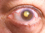
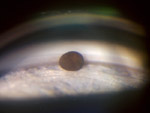
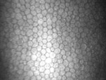
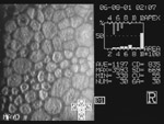
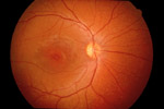
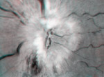
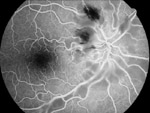
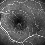
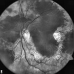
| Timothy Bennett Ophthalmic photography has long played an important role in the documentation and diagnosis of ocular diseases. Like other medical or scientific imaging disciplines, ocular photography is used to record medical conditions, track disease progression, and create illustrations for publication and education. The primary role of ophthalmic imaging however goes well beyond documentation in its ability to aid in diagnosis of a broad range of eye conditions.
|
Introduction
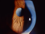
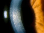
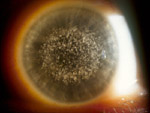
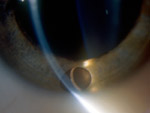
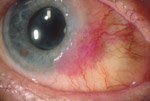
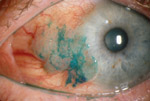
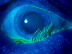
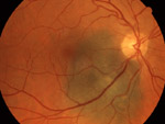
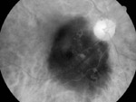
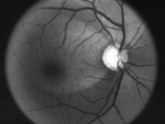
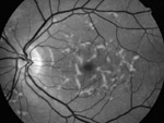
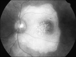
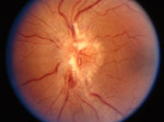
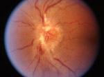
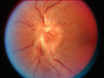
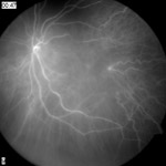
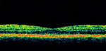
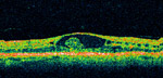
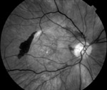
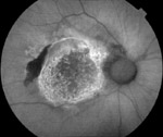
The history of ocular photography dates back to the late 1800’s when Jackman and Webster described a technique for photographing the retina of a living human subject (Saine 1993). The next fifty years witnessed a slow advancement in instrumentation and techniques. Photographic results were mostly inadequate due to slow film speeds, long exposures, and inconsistent light sources. In the 1950s electronic flash and 35mm cameras were adapted to ophthalmic instruments and modern ophthalmic photography was born. There is a compelling connection between this photographic discipline and our subject, the human eye; a connection that goes beyond the obvious parallels between eye and camera, cornea and lens, iris and aperture, retina and film. We use the visual art of photography to identify problems in another visual system - the eye itself. Optical instruments used to examine or photograph the eye often utilize the optics of the subject eye itself to help in visualizing the target pathology. Ophthalmic photography can at times be either simple or incredibly complex. Ocular tissues can be opaque, translucent, or transparent. Enhancement of anatomic features is often achieved through lighting techniques, but sometimes, vital stains, fluorescent dyes, monochromatic light, or specialized optical devices or techniques are needed to adequately document subtle pathology. The following is a brief overview of the techniques being used in ophthalmic photography today. External Ocular Photography Perhaps the most obvious but least specialized type of ophthalmic photography is what is termed “external photography”. Conventional macro photography equipment and techniques are used to document the external, rather than internal appearance of the eyes and surrounding lid and facial structures (Christopherson 1981, Wong 1982, Cunningham 1998, Merin and Rice 1998). It is commonly used to document lesions of the eye or surrounding tissues, demonstrate facial nerve anomalies, and record pre and post surgical alignment of the eyes or eyelids (Figure 1). Single-lens-reflex (SLR) cameras are used to avoid parallax between lens and viewfinder and they offer a variety of compatible lens and electronic flash choices. Magnification for routine external ocular photography ranges from full-face up to life-size on 35mm film. Dedicated macro lenses are the best choice to provide this range and facilitate repeatable magnification settings. Auxiliary electronic flash units with a variable positioning system provide directional lighting that can be adjusted tangentially to demonstrate texture and elevation or moved to an axial position to illuminate a cavity or to accurately render skin color with even lighting. Digital SLRs are the best tool for high-quality external photography. In addition to the inherent advantages of using an SLR for magnification and composition, the LCD screen provides instant feedback on the quality and position of lighting, eliminating the need for a continuous modeling light. Photographers can easily view the results and adjust the flash position and intensity to obtain the desired lighting effects based on the specific subject or pathology. Motility photographs are a series of external photographs showing both eyes together in various positions of gaze. They are used to demonstrate alignment or misalignment of the eyes due to imbalanced extraocular muscles or other disorders that can obstruct or limit normal eye movement. In addition to still images these eye movement disorders are sometimes documented with video. Slit-lamp PhotographyAlthough external photography can capture views of the conjunctiva, cornea and iris with magnifications of up to 2x life size, most high magnification photography of the anterior segment of the eye is done with the use of a photo slit-lamp. The photo slit-lamp is a variation of the slit-lamp biomicroscope routinely used by eye care professionals to light and examine structures in the eye at magnifications up to 40x (Wong 1982, Cunningham 1998, Martonyi et al, 1985). Slit-lamp photography, or as it’s also known photo slit-lamp biomicrography, offers the best opportunity for ophthalmic photographers to demonstrate their photographic skills and creativity. It is a technically and aesthetically challenging discipline that requires a good understanding of composition, magnification, lighting principles and precise exposure control. The slit-lamp is a horizontally mounted binocular microscope with a specialized lighting system that allows visualization of the transparent and translucent structures in the eye. It derives its name from the slit illuminator that applies the principles of Koehler illumination to an optical condensing system to deliver an adjustable beam of light that is focused at the same plane as the microscope. The slit illuminator and the biomicroscope pivot on the same axis to maintain a parfocal relationship. Photo slit-lamps use beamsplitters to direct image-forming light to a camera mounted on the instrument, or in some cases two cameras to provide stereo capture. Electronic flash illumination is delivered through the same condensing optics as the tungsten slit illuminator. Magnification at the film plane is adjustable from approximately 0.7x up to around 5x, depending on the specific instrumentation. The slit beam can be precisely controlled and adjusted from a round or wide rectangular beam down to a very thin slit. One could think of the slit illuminator as a mini studio light with an aperture that can be widely adjusted to limit or direct light output like barn doors on studio lights. A secondary fill light is often available to add background illumination and adjust lighting ratios. Slit-lamp photography is a complex task. It often requires a series of static images to simulate the cumulative effect of a dynamic slit-lamp examination that is accomplished by panning the microscope across the cornea while simultaneously focusing through various structures and swinging the slit illuminator to highlight areas of interest. Still images must be focused at each layer of interest and care must be taken to eliminate flare or reflections that would normally be ignored in the course of routine examination. Lighting techniques fall into two basic categories, direct and indirect. Direct focal illumination can be delivered axially, or tangentially to produce highlights and shadow. Specular reflection can be used to detect surface irregularities in highly reflective structures. A very thin focal beam is often employed to create a narrow cross-sectional view or “optical section” of the normally transparent cornea and lens. Indirect illumination can take on many forms. Iris transillumination, sclerotic scatter, and retroillumination of the cornea or lens are lighting techniques that are accomplished by bouncing or scattering light off other anatomical structures such as the iris, retina, and sclera (Figure 2). Vital stains may be used as an adjunct to slit lighting techniques to enhance visibility of certain ocular surface disorders (Martonyi et al, 1985, Bennett and Miller 2002). Topical applications of rose bengal, lissamine green, or fluorescein can be applied to stain areas of missing or devitalized cells in the cornea and conjunctiva (Figure 3). These dyes are best photographed using diffuse or broad beam, focal illumination. Fluorescein staining can be illuminated with white light to demonstrate yellow staining or with blue light to cause excitation and fluorescence of the dye-stained areas. Gonio PhotographyAuxiliary lenses are sometimes used in concert with a photo slit-lamp to photograph inner structures of the eye that cannot be directly visualized with the slit-lamp (Wong 1982, Martonyi et al, 1985, Curtis 2004). The most common lens type is the gonio contact lens that utilizes internal mirrors angled at approximately 60° to provide observation of the filtering angle of the anterior chamber (Figure 4). The anterior chamber is the space between the cornea and iris, and the filtering angle is the junction of the peripheral cornea, peripheral iris, and sclera. Examination of the angle is important in the detection of structural abnormalities that can contribute to progression of glaucoma. Gonio photography is the most complex and difficult photographic procedure in ophthalmology. Methylcellulose is used as an optical medium between the contact lens and cornea after the eye has been anesthetized. Bubbles in the methylcellulose can interfere with photographic composition. Stray reflections from the mirror or front surface of the contact lens can cause flare and unwanted artifacts. Given the technical challenges associated with this technique, it is not performed on a routine basis by most ophthalmic photographers. Specular MicroscopySpecular microscopy is a variation of slit lamp photography that utilizes specialized single-purpose instruments to image the inner surface of the cornea (Wong 1982). The corneal endothelium is comprised of a single layer of flat transparent cells that are responsible for pumping fluid out of the cornea to maintain its transparency. High magnification and specular reflection is necessary to delineate the cell borders to detect cell density and morphology, which are indicators of corneal health (Figure 5). Magnifications range from 20x to 200x. Traditionally, specular microscopes required contact with the patients’ cornea. The latest instruments utilize non-contact microscopy with semi-automated digital analysis of cell counts and morphology. Fundus PhotographyThe ocular fundus represents the most important subject in ophthalmic photography. The fundus is the inside back wall of the eye and includes the retina, optic nerve head and choroid (Figure 6). Fundus imaging presents some interesting challenges. Our goal is to photograph anatomic structures that can be measured in microns, with enough detail to make diagnostic decisions. All this must be done through the pupil, an opening in the iris just a few millimeters in diameter. Imagine peering through a keyhole into a darkened, curved room that’s a little over an inch in length. In order to visualize the opposite wall of this small chamber, we must illuminate it by shining light through the same small opening we are peering through. This challenge requires a specialized optical instrument, the fundus camera. The fundus camera is a horizontally mounted instrument with an internal electronic flash and an attached 35mm SLR or digital sensor (Tyler et al, 2004). The light needed to illuminate the fundus is delivered axially. The optical system of the fundus camera projects a ring of light from the internal strobe through the dilated pupil. The ring shape allows a separation of the outgoing and incoming illumination. The ring fills the outer pupil with light that reflects off the retina, exits the pupil through the center of the ring, and continues through the optics of the fundus camera to form an image of the fundus at the film plane. Fundus cameras are often described by their optical angle of view. An angle of 30 degrees is considered the normal angle of view and creates a film image 2.5 times life size. Fixed-angle cameras usually offer the sharpest optics, but variable-angle cameras provide wide-angle capabilities between 45 and 60 degrees. Wide-angle cameras need to illuminate a broader area of retina, requiring a more-widely dilated pupil to accommodate a larger ring of light. Peripheral fundus photography can be particularly challenging. When the eye is rotated to the desired peripheral field of view, the opening in the pupil appears elliptical, making it difficult to fit the entire illuminating beam within its borders. The off-axis angle also causes the image-forming light rays to pass through a flatter portion of the cornea, which will change focus and cause some distortion. Monochromatic Fundus Photography Monochromatic fundus photography is the practice of imaging the ocular fundus with the use of colored or monochromatic illumination (Figure 7). In 1925, Vogt described the use of green light to enhance the visual contrast of anatomical details of the fundus (Vogt 1925). The technique is still commonly used today in combination with fundus photography. Monochromatic fundus photography is based on two basic principles of light and photography: the use of contrast filters to alter subject tones in black and white photographs and the increased scattering of light at shorter wavelengths. By limiting the spectral range of the illuminating source, the visibility of various fundus structures can be enhanced (Behrendt and Slipakoff 1976, Delori et al, 1977, Miller and George 1978, Ducrey et al, 1979). This technique is most effective when combined with high-resolution black-and-white film or digital sensors. Blue light increases visibility of the anterior retinal layers, which normally are almost transparent in white light. Blue light is absorbed by retinal pigmentation and blood vessels, providing a dark background against which the specular reflections and scattering in the anterior layers of the fundus is enhanced. Scattering in the ocular media can limit the effectiveness of these wavelengths. The retinal nerve fiber layer, the internal limiting membrane, retinal folds, cysts and epiretinal membranes are examples of semi-transparent scattering structures that are enhanced with short wavelength illumination (Figure 8). Because of excessive scattering at very short wavelengths, blue-green (cyan) filters of 490nm are often employed. Green light is also absorbed by blood, but is reflected more than blue light by retinal pigmentation. There is less scatter than with shorter wavelengths, so media opacities aren’t quite as troublesome. Green light provides excellent contrast and the best overall view of the fundus. It enhances the visibility of the retinal vasculature, and common findings such as hemorrhages, drusen and exudates (Figure 9). For this reason, green filter "red-free" photos are routinely taken as baseline images in conjunction with fluorescein angiography. In red light, the retinal pigmentation appears more transparent revealing the choroidal pattern. Overall fundus contrast is greatly reduced with red illumination. Retinal vessels appear lighter and become less obvious at longer wavelengths. The optic nerve appears lighter and almost featureless. Red light is useful for imaging pigmentary disturbances, choroidal ruptures, choroidal nevi and choroidal melanomas (Figure 10). Stereo ImagingStereo images enhance diagnostic information by providing a visual sense of depth and realism beyond ordinary two-dimensional photographs. The use of this technique in ophthalmology dates back as far as 1909, but it wasn’t until the 1960’s that stereo fundus photography became widely employed after Lee Allen described a practical technique for sequential stereo fundus photography (Allen 1964). This technique is another good example of how we can take advantage of the optical interaction between the subject eye and camera. Laterally shifting the fundus camera a few millimeters between sequential photographs causes the illuminating beam of the fundus camera to fall on opposite slopes of the cornea. The resulting cornea-induced parallax creates a hyper-stereoscopic effect that is evident when the sequential pair of photographs is viewed together. Stereo pairs are particularly useful in identifying the anatomic location of pathologic findings in retinal photographs. Stereo imaging is a standard protocol for many clinical trials investigating treatment of retinal diseases. Stereo imaging techniques have also been employed for slit-lamp biomicrography and to a lesser extent, external photography. There are a variety of optical stereo viewers available for viewing side-by-side 35mm film images on a light box, or digital images on a computer monitor. All stereo viewing devices are designed to deliver the separate stereo images simultaneously but independently to each eye allowing the brain to fuse the pair. The common use of digital projection has resulted in a resurgence in stereo projection using the color anaglyph technique (Bennett 2005). This technique works very well with grayscale angiographic images. A stereo pair can be digitally color encoded as a single image using image-editing software. Instead of employing optics or polarization to display a stereo effect, the anaglyph method uses complementary colors to encode and deliver stereo information (Figure 11). Digital imaging software facilitates accurate and effective registration of anaglyph stereo pairs. Anaglyph stereo pairs can be viewed with inexpensive eyewear either on a computer monitor or projected with an LCD projector and are useful in educational settings. Fluorescein AngiographyOphthalmic photography has at times seemed almost synonymous with fluorescein angiography. For over four decades, ophthalmologists have relied on fluorescein angiography as an important tool in the understanding, diagnosis and treatment of retinal disorders. Fundus cameras are equipped with a matched pair of exciter and barrier filters along with a fast recycling electronic flash tube that allows a capture rate of up to one frame per second. Narrow band-pass interference filters are utilized to allow maximum transmission of peak wavelengths and limit crossover of transmission curves. The exciter filter transmits blue-green light at 465-490nm, the peak excitation range of fluorescein. The barrier filter transmits a narrow band of yellow at fluorescein’s peak emission range of 520-530nm, effectively blocking all visible wavelengths but the specific color of fluorescein. This technique facilitates the in-vivo study of the retinal circulation (Figure 12) and is particularly useful in the management of diabetic retinopathy and macular degeneration, two leading causes of blindness. Angiograms are used to determine the extent of vascular damage, to develop treatment plans or to monitor the results of treatment. Used as a guide for laser treatment, fluorescein angiography has benefited countless patients. Angiography also plays an important role in clinical research, advancing the understanding of retinal vascular disorders and potential treatment modalities. A number of multi-center clinical trials use fluorescein angiography to investigate new treatment options to combat retinal disease. As new therapeutic modalities are developed, fluorescein angiography will continue to play an important role in the management of common retinal conditions. On rare occasions, fluorescein angiography of the iris or other anterior structures may be of value to ophthalmologists. This can be accomplished by using a fundus camera with a plus-diopter lens, but images may be slightly distorted. Alternately, fast-recycling power packs and matched filter sets can be adapted to a photo slit-lamp to achieve high-quality results. Scanning Laser OphthalmoscopyFluorescein angiography can also be recorded using a confocal scanning laser ophthalmoscope (SLO) in place of the conventional fundus camera (Figure 13). The confocal SLO uses a laser beam of the appropriate excitation wavelength to scan across the fundus in a raster pattern to illuminate successive elements of the retina, point-by-point (Woon et al, 1990, Clark 2002). The laser can deliver a very narrow wavelength band for more efficient excitation of fluorescence than the flash illumination generated by a fundus camera flash tube. A confocal aperture is positioned in front of the image detector at a focal plane conjugate to the retina, effectively blocking non image-forming light. The confocal optical system and laser illumination combine to produce high contrast, finely detailed images. The laser scan rate is synchronized at a frame rate compatible with digital video display, providing a continuous high-speed representation of the flow dynamics of the retina and choroid. This can be especially useful when documentation of the very early filling stages is necessary, such as in identification of CNV feeder vessels. The scan rate is synchronized at a frame rate compatible with digital video display, providing a continuous real-time representation of the flow dynamics of the retina and choroid. ICG Angiography Digital technology facilitates the use of another fluorescent dye, indocyanine green (ICG), for retinal and choroidal angiography. The choroid is a highly vascular structure found immediately behind the retinal pigment epithelium (RPE), which acts as a physical barrier between the retinal vascular system and the choroidal vascular system. The view of the choroid is normally obscured by the RPE, both in clinical appearance and during fluorescein angiography. With peak absorption and emission in the near-infrared range at 805nm and 835nm respectively, ICG provides greater transmission through the RPE and hemorrhage than the visible wavelengths used in fluorescein angiography (Figure 14). ICG also binds more completely with blood albumins, so it normally remains within the fenestrated walls of the choriocapillaris, unlike fluorescein, which leaks freely from these vessels. ICG choroidal angiography was first performed in humans in 1972, but results were limited by insufficient sensitivity of available infrared films (Flower and Hochheimer 1972). In the early 1990’s, two groups reported improved results with commercially available digital angiography systems (Yannuzzi et al, 1992, Guyer et al, 1992). The infrared sensitivity of available CCD cameras was combined with new lens coatings that improved infrared transmission for ICG angiography. In the early to mid 1990’s, enthusiasm for this procedure exceeded its practical applications (Flower 1992). Use of this technique waned by the late 1990’s as clinical research had defined a vital, but limited role for ICG angiography as an adjunct to fluorescein angiography. Today, ICG is used in combination with fluorescein angiography in a limited number of diagnoses where choroidal circulation is effected, such as macular degeneration (Stanga et al, 2003). The goal in macular degeneration is to identify choroidal feeder vessels that can be treated with a laser to prevent damage to the retina (Shiraga et al, 1998). The current trend however, is the use of medical therapies in place of laser treatment for many retinal conditions. As research into new medical treatments continue, ICG is likely to be used more as a research tool rather than for routine clinical use. Optical Coherence Tomography Optical coherence tomography (OCT) is a relatively new imaging procedure that is useful in the diagnosis of several retinal disorders that have traditionally been imaged with fundus photography or fluorescein angiography (Puliafito et al, 1995, Costa et al, 2006). OCT imaging provides direct cross-sectional images of the macula, retinal nerve fiber layer and optic nerve for objective measurement and clinical evaluation in the detection of retinal diseases and glaucoma. It is particularly useful in the detection of macular holes, cystoid macular edema, subretinal fluid, and retinal pigment epithelial detachments (Figure 15). Its greatest value however, may lie in the ability to quantify and monitor change in retinal thickness due to macular edema from diabetic retinopathy or other causes. OCT technology was originally developed at the Massachusetts Institute of Technology in 1991 and is based on the principle of low coherence interferometry. The principle is similar to ultrasound, except that near-infrared light (820nm) is used instead of sound. This difference permits resolution of ≤ 10µm, which is 10 times better than ultrasound. A superluminescent diode light is directed at both the eye and a reference mirror at a known spatial location. The time-of-flight delay of light backscattered from different layers of the retina is measured and analyzed. Retinal thickness is calculated by processing the cross-sectional images using computer algorithms to detect tissue boundaries by searching for the highest rates of change in reflectivity. Although the technology has been available for over a decade, OCT was mostly used in academic settings or for research applications until the release of the Carl Zeiss Meditec OCTIII in 2002. This instrument represents the third generation of OCT technology in ophthalmology. The evolution of the technology, in the form of increased resolution and ease of operation, has matured to the point where OCT imaging is both practical and affordable. Since its introduction OCT has rapidly gained widespread acceptance and for certain retinal conditions, OCT is now the diagnostic procedure of choice. Compared to angiography, OCT is less expensive, less invasive, faster, easy to perform, and well tolerated. The non-invasive procedure can be conducted in about 10 minutes without dilation or discomfort to the patient (Hoffmeyer 2003). Anecdotal reports suggest a decline in the utilization of fluorescein angiography during the rapid widespread acceptance of OCT. This trend is likely to continue as treatment of diabetic macular edema and macular degeneration shift from traditional laser treatment (requiring a fluorescein angiogram) to the recently favored medical management of these conditions with injections of intraocular medications, which can be can be monitored with OCT. The popularity of OCT has also resulted in a need for education in both performing OCT, and interpretation of results. New instruments are currently being developed by a number of manufacturers. Advances in technology that use spectral or Fourier domain OCT techniques, promise improvements in resolution and acquisition speed, as well as 3-D representations of retinal structures. Fundus Autofluorescence Fundus autofluorescence is a recently developed non-invasive imaging technique for documenting the presence of lipofuscin in the retinal pigment epithelium (RPE). Lipofuscin is a fluorescent pigment that accumulates in the RPE as a metabolic byproduct as the eye ages. When excited with short wavelength illumination, lipofuscin granules autofluoresce, exhibiting a broad emission spectrum from 500 to 750 nm with peak emission at about 630 nm (Delori et al, 1995). The original technique uses a confocal scanning laser ophthalmoscope with the excitation wavelength set at 488 nm and a barrier filter at 500 nm or 520 nm (von Ruckman et al, 1995). Several frames are captured with the SLO, then aligned and averaged to reduce noise. Because several frames are required, image quality may be affected by eye movement during capture. More recently, digital fundus-camera based systems have been developed which use high-sensitivity monochrome sensors with an excitation filter at 580 nm and a barrier filter at 695 nm to avoid confounding autofluorescence from the crystalline lens (Spaide 2003). Both systems require significant amounts of light and increased gain settings to achieve adequate exposure and are subject to image noise. Despite the disparity in excitation wavelength and barrier filters between the SLO and fundus camera systems, these two techniques obtain results that are quite similar in appearance. Autofluorescence imaging has the potential to provide useful information in conditions where the health of the RPE plays a key role. Hyperfluorescence is a sign of increased lipofuscin accumulation, which may indicate degenerative changes or oxidative injury. Areas of hypofluorescence indicate missing or dead RPE cells. Geographic atrophy that appears as a window defect in fluorescein angiography, will appear dark in autofluorescent imaging (Figure 16). A number of investigators are exploring potential applications of this imaging technique in a variety of retinal diseases. SummaryOphthalmic diagnostic imaging enhances the understanding, diagnosis and treatment of a wide variety of ocular disorders. Treatment plans derived from ophthalmic images have benefited countless patients, as ophthalmologists use images for decision making purposes on a daily basis, and in some cases, rely on photographs as a “road map” to guide laser therapy. There is room for creativity and aesthetics in this field and many ophthalmic images transcend their scientific purpose and achieve artistic merit, but it can be heartbreaking when the most photogenic or aesthetically pleasing subjects present themselves because a patient’s vision is severely compromised. Enthusiasm for creative imaging can suffer in the context of tragic loss of vision. This is balanced however, against those times when an imager captures great images that help preserve a patient’s vision. Unfortunately not all images will be of sufficient quality to warrant public display or publication. The challenge for ophthalmic photographers is to provide consistent clinical images of adequate diagnostic quality, even under adverse conditions. By providing support for education, research, and clinical eye care activities, ophthalmic photographers have been an integral part of the professional eye care community for decades. As new diagnostic imaging and treatment modalities are developed, the role of the ophthalmic imager will evolve and continue to play an important role in the preservation of sight. Part two of this overview will extend beyond technique and focus on the evolution of ophthalmic photography as a profession. Discussion will include: education and the role of certification, the impact of digital imaging, current trends in the profession, and an introduction to the Ophthalmic Photographers’ Society. References Author’s note: Reference/tutorials on Ophthalmic Photography techniques are available on the Ophthalmic Photographers’ Society website at: http://www.opsweb.org/Op-Photo/Op-Photo.htm Topics include: Fundus Photography, Monochromatic Fundus Photography, External Photography, Photo Slit Lamp Biomicrography, Specular Micrography, Fluorescein Angiography, and ICG Angiography. Searches can be performed on the table of contents for all issues of the Journal of Ophthalmic Photography from 1978 through the date of the last update at http://www.opsweb.org/Publicat/Journal/JourSrch.htm. Beginning with Volume 19:3 (December 1997), all citations are linked to PDF files containing the associated article. Allen L., 1964. Ocular fundus photography: Suggestions for achieving consistently good pictures and instructions for stereoscopic photography. Am J Ophthalmol 57:13–28. Behrendt T, Slipakoff E., 1976. Spectral reflectance photography. Int Ophthalmol Clin 16:95-100. Bennett T.J., Miller G., 2002. Lissamine green dye – an alternative to rose Bengal in photo slit lamp biomicrography. J Ophthalmic Photography 24:74-77. Bennett T.J., 2005. Stereo anaglyph preparation for PowerPoint. J Ophthalmic Photography 27:38-45. Christopherson K.W., 1981. External eye photography: equipment and technique. J Ophthalmic Photography 4:28. Clark T.M., 2002. Scanning laser ophthalmoscopes. In: Saine PJ, Tyler ME, eds. Ophthalmic Photography: Retinal Photography, Angiography and Electronic Imaging. 2nd ed. Boston, Butterworth-Heinemann, 2002:306-321. Costa R.A., Skaf M., Melo L.A. Jr, et al., 2006 Retinal assessment using optical coherence tomography. Prog Retin Eye Res 25:325-353. Epub. Cunningham D., 1998. Clinical Ocular Photography. Thorofare, NJ Slack Inc. Curtis R., 2004. Goniophotography. J Ophthalmic Photography 26:13-19. Delori F.C., Gragoudas E.S., Francisco R., et al., 1977. Monochromatic ophthalmoscopy and fundus photography. The normal fundus. Arch Ophthalmol 95:861-868. Delori F.C., Dorey C.K., Staurenghi G., et al., 1995. In vivo fluorescence of the ocular fundus exhibits retinal pigment epithelium lipofuscin characteristics. Invest Ophthalmol Vis Sci 36:718-729. Ducrey N.M., Delori F.C., Gragoudas E.S., 1979. Monochromatic ophthalmoscopy and fundus photography. II. The pathological fundus. Arch Ophthalmol 97:288-293. Flower R.W., Hochheimer B.F., 1972. Clinical infrared absorption angiography of the choroids. Am J Ophthalmol 73:458-459. Flower R.W., 1992. Choroidal angiography today and tomorrow. (Guest editorial) Retina12:189-190. Guyer D.R., Puliafito C.P., Mones J.M., et al.,1992. Digital indocyanine-green angiography in chorioretinal disorders. Ophthalmology 99:287-290. Hoffmeyer G.C., 2003. MacPac: a systematic protocol for OCT scanning of macular pathology. J Ophthalmic Photography 25:70-76. Martonyi C.L., Bahn C.F., Meyer R.F., 1985. Clinical Slit Lamp Biomicroscopy and Photo Slit Lamp Biomicrography. Ann Arbor, MI, Time One Ink, Ltd, 1985. Merin L.M., Rice C.D., 1998. An improved method of facial photography for oculoplastic patients. J Ophthalmic Photography 20:16-18. Miller N.R., George T.W., 1978. Monochromatic (red-free) photography and ophthalmoscopy of the peripapillary retinal nerve fiber layer. Invest Ophthalmol Vis Sci 11:1121–1124. Puliafito C.A., Hee M.R., Lin C.P., et al., 1995. Imaging of macular diseases with optical coherence tomography. Ophthalmology 102:217-229. Saine P.J., 1993. Landmarks in the development of fluorescein angiography. J Ophthalmic Photography 15:17-23. Shiraga F., Ojima Y., Matsuo T., et al., 1998. Feeder vessel photocoagulation of subfoveal choroidal neovascularization secondary to age-related macular degeneration. Ophthalmology 105:662-691. Spaide, R.F., 2003. Fundus autofluorescence and age-related macular degeneration. Ophthalmology 110:392-399. Stanga P.E., Lim J.I., Hamilton P., 2003. Indocyanine green angiography in chorioretinal diseases: indications and interpretation: an evidence-based update. Ophthalmology 110:15-21. Tyler M.E., Saine P.J., Bennett T.J., 2004. Practical Retinal Photography and Digital Imaging Techniques. Philadelphia, Butterworth-Heinemann. Vogt A. 1925. Die Ophthalmoskopie im rotfreiem licht. GraefSaemisch Handbuch der gesamten Augenheilkunde. Berlin, Springer Verlag, vol 3. von Ruckman A., Fitzke F.W., Bird A.C., 1995. Distribution of fundus autofluorescence with a scanning laser ophthalmoscope. Br J Ophthalmol 79:407-412. Wong D., 1982. Textbook of Ophthalmic Photography. Inter-Optics Publications. New York. Woon W.H., Fitzke F.W., Chester G.H., et al., 1990. The scanning laser ophthalmoscope: basic principles and applications. J Ophthalmic Photography 12:17-23. Yannuzzi L.A., Slakter J.S., Sorenson J.A., et al., 1992. Digital indocyanine green videoangiography and choroidal neovascularization. Retina 12:191-223. Timothy J. Bennett, CRA, FOPS, is an ophthalmic photographer in the Penn State University Department of Ophthalmology at the Milton S. Hershey Medical Center. Mr. Bennett has over 25 years experience working in university-based academic medical centers. He is a nationally recognized author, lecturer and educator in the field of ophthalmic photography. Mr. Bennett holds current certification as a Certified Retinal Angiographer, is a Commissioner of the Joint Commission on Allied Health Personnel in Ophthalmology, and has been recognized for his contributions to the profession by being named a Fellow of the Ophthalmic Photographers Society. He has served on the OPS Board of Certification, the OPS Board of Directors, and is currently President of the Ophthalmic Photographers’ Society. Email: tjbennett@psu.edu |
Copyright
2007, The Journal of Biocommunication, All Rights Reserved
Table
of Contents for VOLUME 32, NUMBER 2